Patterned Noise Removal With FFT Filtering

When one thinks of noise in a digital image one usually thinks of a random distribution of undesired pixels or other elements. But noise can also assume a regular pattern of some sort, equally undesirable. For example, the production of printed material uses a halftone method which, when scanned into digital image, results in a regular noise pattern called moire (in RGB color) or just halftone noise in a bw/grayscale image.
Fortunately, such patterned noise can be very effectively eliminated with a filtering technique that is based on FFT, or the fast fourier transform. This article describes the essential features of this noise-removal method using GNU/Linux software tools.
What is the Fourier transformation?
It is well beyond the scope of this article to explain the mathematics of the FFT, which are quite extensive, but there are many sources available that provide an introduction:
- FFT Tutorial
- FFT Introduction
- Fred Weinhaus FFT Page
- Paul Bourke FFT Filtering
- Fourier Transform of Images (PDF)
Basically, a digital image exists in a so-called intensity "space." (A "space" is a common math abstraction.) In other words, each image pixel represents the intensity of light that has fallen on the camera sensor (for color images there are actually three intensities for RGB). To reproduce the image a computer will attempt to display an equal intensity using the monitor. However, an image can also exist in a frequency space, wherein each pixel represents a spatial frequency, which is a measure of intensity variations across a unit of physical space (aperture). It is the FFT that acts as a transform between the two types of image spaces and that allows highly selective filtering, based on spatial frequencies, to be accomplished.
Consider the following image on the left which is formed by a sine wave spatial intensity pattern at a certain frequency that is diagonally spread across the image. The sine wave troughs and peaks of intensity are plainly visible. The image on the right is the FFT transform of the left image. Note that most pixels, i.e. frequencies, are absent (black) but the pixels corresponding to the sine wave frequency are quite visible and also oriented in the same diagonal direction (the fact that there are two, mirror images, of these frequencies is due to the fact that the FFT is based on complex numbers). Also notice that not just a single frequency is shown but rather a series of frequencies of diminishing amplitude. This is merely an artefact resulting from the imperfection of representing a continuous sine wave in a digitized manner. (For best viewing, click for the full-sized image.)
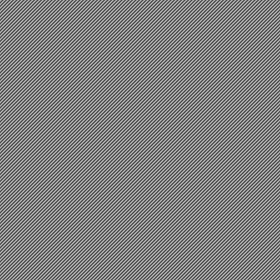
Diagonally Oriented Across Aperture

(enhanced for human visibility)
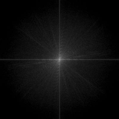
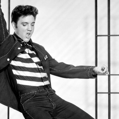
Shown next is an ordinary image (Elvis Presley performing Jailhouse Rock) and its FFT transform. In this case the pixels, or frequencies, seem very dense and randomly distributed but that is because the original image is composed of continuous grades of intensity across many directions which results in a dense, seemingly random, frequency composition.

(click for full size)
(click for full size)
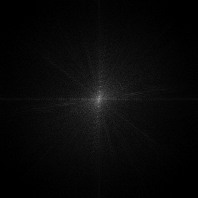
Let's now compose, or overlay, the above sine wave image over the previous image to create an image with patterned noise. On the left is our overlay of a noisy Elvis. The rightmost image is the resultant FFT of the combined images. Most pixels seem randomly oriented but the added sine wave frequencies are readily apparent as two bright pixels. (Click for full size to better observe the diagonal frequencies.).
composite -blend 50% patterned_noise.png Elvis.png Elvis+noise.png

(click for full size)
(click for full size)
The idea should be clear. If we can somehow remove, or mask, the frequencies that correspond to the regular noise pattern then we can effectively eliminate it. What follows will be a demonstration of how this masking is accomplished.
But before we entertain the details, let's quickly clean up Elvis.
Since the noise was artificially added we know the exact frequency components from our original noise spectrum. A mask is created to filter the undesired frequencies by simply inverting, or taking the "negative," of the noise spectrum image. The black areas of the mask will remove the corresponding frequencies and the white areas will keep them. Next is shown, at left, the mask image and, at right, the result of applying the mask. Elvis is indeed noise-free but there remains a trace of some low frequency artefacts, barely discernible, due to the imperfections inherent in the process.

(click for full size)
(click for full size)
The FFT Filtering Technique
1) Produce the FFT Transform and Spectrum
The GNU/Linux software that is used is the ImageMagick suite of command-line utilities:
ImageMagick must be built with FFTW, or the Fastest Fourier Transform in the West, libraries:
ImageMagick must also be built with high bit depths (HDRI) enabled to accurately store the FFT data. The IM docs at the above link provide the details on how to properly build the software (many GNU/Linux distros may already build IM this way).
The command sequence to create the FFT spectrum of an image is shown next:
	f=image_file_name

	MAG=10000

	convert -depth 32 -define quantum:format=floating-point -fft +adjoin ${f%.*}_fft_%d.tif

	convert ${f%.*}_fft_0.tif -contrast-stretch 0 -evaluate log $MAG ${f%.*}_spectrum.tif
These first command will convert the image file and compute the FFT data as two images. The FFT process always produces a frequency-space image and a phase-space image. For filtering purposes only the frequency-space is relevant, but both must eventually be used to reconstruct the filtered image.
If the original file was named "some_img.tif" the FFT transform images will be named "some_img_fft_0.tif" and "some_img_fft_1.tif" with the former representing the frequency space.
The second command essentially magnifies the frequency vales by the factor MAG. This is necessary because most frequency values are very small in magnitude and would not be visible to the human eye when displayed on a monitor. This magnified image, named "some_img_spectrum.tif" becomes our frequency spectrum, and also, after suitable processing, our frequency mask.
Note that the TIFF format is used the processing because only TIFF can store data as 32-bit floating point values which are needed for maximum accuracy. After the final processing step the TIFF file can easily be converted into any other desired format.
Let us now apply these commands to a image with some nasty patterned noise which is shown next.
At the left we see patterned noise that seriously degrades the image. Using ImageMagick as above the FFT spectrum of this image is created and shown on the right. (The images should be viewed at full size to best appreciate the characteristics.)
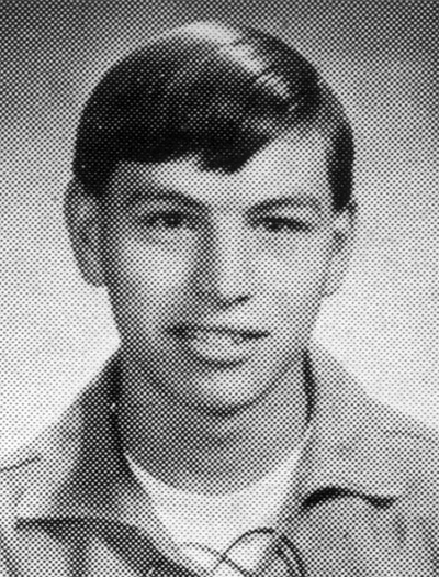
(click for full size)
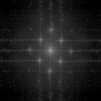
(click for full size)
The regular noise pattern is recognized by the series of very bright, and highly localized, areas that are distributed in a rectangular fashion. Again, there is not just a single frequency but a diminishing series of frequencies.
How do I know that these areas represent the noise?
It requires a bit of practice by examining a lot of FFT transformations, but highly regular noise at given orientations is usually very apparent.
2) Creating the Frequency Mask
The spectrum image is the basis for the FFT filter mask creation. It will be modified to produce the mask image. The goal is to create a mask that will remove the frequency bits of the patterned noise and that will keep every other frequency.
The best masks can only be created by careful manual editing but an automated method can in many cases lead to very good results. In what follows a basic and quick automated method will be described.
The most important aspect of creating a mask is to always preserve the low image frequencies, i.e. those that are clustered near the zero DC value at the image center. These freqs contain most of the discernible image information. The easiest way to do this is to draw on the spectrum image a circular disc of a given radius at the center. The radius is chosen so that the disc will not intersect any of the obvious patterned noise freqs. (In this particular example, the ideal radius is determined, by a visual inspection of the spectrum image, to be about 100 pixels.)
Next the spectrum, containing the drawn disc, is thresholded at a suitable value to intensify the patterned noise freqs and to hopefully exclude every other freq. The exact valuse for thresholding is a matter of some trial and error but I find that 20% is usually a good choice. The interested reader, however, is encouraged to always experiment.
The thresholding also serves to create a bitonal image from the original spectrum data and that is what is desired. The bitonal image, containing only 1's and 0's, will be multiplied by the original FFT transform images and this will either preserve the respective frequency/phase value (multiply by 1) or eliminate it (multiply by 0).
But, lastly, in order to do the multiplication properly, we need to invert, or negate, our thresholded image containing the circular disc.
All three of the previous steps, drawing the center circle, thresholding, and bit inversion, can be accomplished with the following command that is applied to our spectrum image:
convert image_spectrum.tif -draw "circle 460,460,550,460" -threshold 20% -negate image_mask.tif
Recall that the FFT transform and FFT specrtum data were stored as a 32-bit FP TIFF image. This command operates on this data to produce a bitonal mask image. The resultant mask, alongside the original spectrum image, is shown next:
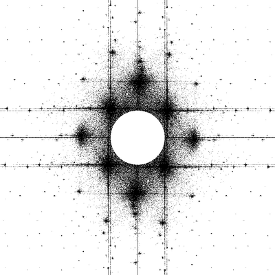
(click for full size)

(click for full size)
3) Apply the FFT Filter Mask
Now that we have our mask filter image we apply to it to the original FFT transforms, i.e. the magnitude and phase images (img_fft_0.tif and img_fft_1.tif). The mask is applied via direct multiplication of the pixel vales followed by an inverse FFT transform. All of this is accomplished with the following ImageMagick command:
convert \( img_mask.tif img_fft_0.tif -compose multiply -composite \) img_fft_1.tif -ift img_filtered.tif
Finally, the filtered result is shown alongside the original noisy image (viewing the full-sized images is recommended to best appreciate the details):
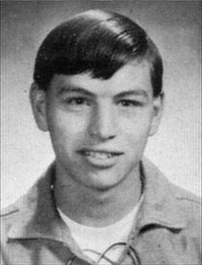
(click for full size)

(click for full size)
Even with this rather crude mask the results are definitely impressive. The patterned noise, which had seriously degraded the original image, has been nearly completely eliminated.
Epilogue
Hopefully this discussion has demonstrated the power of the FFT filtering to remove patterned noise from images.
The reader may be wondering whether the FFT can be applied to color images as well. The answer is that ImageMagick can process the FFT of color images in the same manner as described above. One will obtain a colored spectrum image that can be processed identically to produce a bitonal mask.
But this demo only begins to illustrate the capabilities of the FFT for image processing. The interested reader is encouraged to explore this area further. With GNU/Linux, many software tools are available to aid in any serious study.